


Analysis of casing treatment`s impact on the axial compressor model stage characteristics
K Tribunskaia and Y V Kozhukhov
Abstract. There are special requirements for the compressors of aircraft engines. They must ensure maximum efficiency in a maximally large stable work zone Due to a high pressure ratio these stages are more susceptible to the losses from radial clearance. One of the approaches to reduce such losses is the application of above-rotor devices. In the following study there is considered the impact of such treatments on the compressor stage performance. Despite the fact that there is a sufficient amount of research about this issue, their results are contradictory. The use of these devices can affect the characteristics of compressor stage performance both positively and negatively. This study was conducted using the methods of computational fluid dynamics and was based on the NASA Rotor-37 geometry model stage. Results were obtained through the comparison of the characteristics of stages with and without above-rotor devices.
Nomenclature
TC – Tip Clearance
Ky – Stall Margin (SM)
– Mass flow rate
π* – Total pressure ratio
k – Specific heat ratio
P – Total pressure
T – Total temperature
Subscripts
pk — Peak Efficiency Point
st — Near Stall Point
SC — Smooth casing
CT — Casing treatment
- Introduction
The purpose of this work is to explore the influence of the casing treatment on the transonic axial compressor stage performance. In reference to the above-rotor devices it should be understood that casing treatments are used in the stage.
During nearly half a century, a large number of above the rotor casing treatments were designed and tested [1, 3, 4, 6, 7]. The main goal of such improvements was to provide the largest stable work zone for transonic axial compressor stages with the minimizing of efficiency losses. According to the researcher`s surveys, the more efficient a casing treatment`s stability margin, the less effective the compressor stage work [1].
High pressure ratio in transonic and supersonic stages provokes leakages through the TC from the suction side. This gap between the casing and the rotor blade is one of the most critical factors, because the efficiency losses from the leak can be from 0.3 to 1.1% of stage efficiency [2].
It should also be noticed that the physical phenomena occurring in the flow path of the transonic compressor such as blade tip stall and tip blockage stall are very dangerous and will negatively affect the compressor performance. [3]
Aerodynamic overloading on the blade of the compressor is increased and the risk of rotation stall or surge. Nowadays there are distinguished several methods that use enhancements to the stator ways to solve the problem of increasing the stability of the compressor. They are divided into active and passive methods. Passive methods include creating a different casing treatments configurations: grooves, honeycomb seals, etc.
- Hembera (etc.) [3] distinguish two categories of the casing treatments according to their shape:
- Circumferential treatment such as circumferential grooves, which are typically axis-symmetric
- Axial treatments such as axial slots, which are non-axis — symmetric
According to the investigation [1] tip injection is another way to increase the stall margin (SM).
Thus, any above-rotor devices must be designed to exclude any low-energy zones (stagnation and blockage zones).
The following activities can minimize the above-mentioned negative effects:
- reducing radial clearance
- the movement of low-energy zone leakages, when you use casing treatments according to the principle of honeycomb seals (axial slots)
- the deflection of the flow direction parallel to the main flow, using, for example, the peripheral annular groove.
- Numerical method
In terms of given task, the two performance parameters was selected: stall margin and adiabatic efficiency. The stall margin is calculated as following for each configuration:
| (1) |
The adiabatic efficiency is calculated as following for each configuration:
| (2) |
- Investigation of the smooth casing
The study presents the investigation of the transonic compressor stage based on the NASA rotor 37 profile geometry (Fig.1). The main design parameters are shown in Table 1. The computational domain (Fig. 2) is divided into two passages – rotor and stator respectively. Design parameters and experimental data were taken from the NASA report [5].
The stator is represented by a smooth surface. The gap between the upper edges of the rotor blades is 0.356 mm.
The impeller peripheral speed is 17188 rpm, pressure ratio (measured at total parameters) is 2.106 and the value of the adiabatic efficiency is as 88.9% at the design point (at the estimated mass flow of 20.19 kg/s).
| Table 1. Stage design parameters | |
| Total temperature, K | 483.35 |
| Total pressure, kPa | 195. 218 |
| Rotation speed, rpm | 17 188 |
| Mass flow rate (), kg/s | 20.19 |
| Tip Mach Number | 0.9 |
| Number of rotor blades | 36 |
| Number of stator blades | 46 |
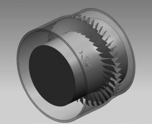
Figure 1. Solid model NASA rotor 37
stage
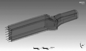
Figure 2. Computational domain3.1. Mesh description
A structured grid is constructed with the ANSYS Turbogrid. A grid-dependency test is performed for the reference design with the various number of nodes. The result of test shows that the «curse» grid contained 530 000 nodes gives less accurate parameter`s values than the «detail» grid with total number of nodes 970 000 for each domain (stationary and rotational).
3.2. Boundary conditions
The working fluid was considered as ideal gas.
The solid boundaries in the computation domain are considered as adiabatic with the hydraulically smooth walls. The periodic boundaries are set at the blade passage interface, and TC was modeled along the passage. Inlet conditional: total pressure, total temperature (Tab.1). The SST turbulence model was used.
3.3. Verification of the received data
10 different modes were investigated for the validation of the obtained results. The stall line was adopted at the normalized mass flow value /=0.91 kg/s. The SM parameter (1) achieved the value 13.56%.
The numerical results are in good agreement with experimental data. Average difference between parameter is up to 3% (Fig.3).
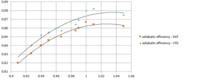
Figure 3. Verification of the CFD results
4.1. Selection of casing treatment configurationInvestigation of the casing treatment
In the article of 1984 Fujuta and Takata [6] considered multiple configurations of casing treatment: axial-skewed and axial-radial slots (Fig.4-5). The result of this study indicates that skewed axial slots casing treatment is the best way to provide the margin of stability. However, the circumferential grooves provides less efficiency losses. Thus, to ensure the stable operation with the least loss of efficiency, it is necessary to combine these two types. According to the Cevik`s [7] survey the triangle shape is the optimal to achieve acceptable SM improvement and prevent the large efficiency losses.
![Figure 4. Axial-skewed and axial-radial slot configuration by Fujuta and Takata (1984) [6]](https://kviht.ru/wp-content/uploads/2017/09/4-3-195x300.png)
Figure 4. Axial-skewed and axial-radial slot configuration by Fujuta and Takata (1984) [6]
![Figure 5. Circumferential groove configurations by Fujuta and Takata (1984) [6]](https://kviht.ru/wp-content/uploads/2017/09/5-3-255x300.png)
Figure 5. Circumferential groove configurations by Fujuta and Takata (1984) [6]
The appearance of investigated casing treatment is shown on Fig.7 shows. Table 2 reflects the main geometric parameters.Selection of casing treatment geometry for the study was by virtue the above-mention and other findings. Another important chose factor was simplicity – the design should be suitable and applicable for the existing geometry with a smooth rotor. For this work was selected annular grooves, triangular shape (Fig.6).
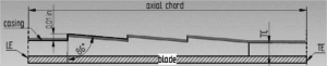
Figure 6. Casing treatment. Front view
| Table 2. Design parameters for the stage with casing treatment | |
| Shape | Triangle |
| Depth | 1×10⁻³ inch |
| Width | 0,6 Axial Chord |
| Groove | 3 |
4.2. Computational model
The structured mesh was generated in ICEM CFD and it was implemented in previous computation domain. The general grid interface (GGI) was used to connect the grooves to the main domain.
- Results and discussion
| Table 3. Obtained performance parameters for the smooth casing and casing with grooves | ||
| Parameters | Smooth casing | Casing with grooves |
| SM, % | 13.56 | 15.63 |
| Adiabatic efficiency peak, | 0.866 | 0.822 |
Figure 8, 9 indicated the Mach number counters on the pre-stall mode (/=0.91 kg/s ).
Noticeably that there are a low speed region (Fig.8). In case of casing treatment this low-energy zone is not so strong (Fig.9) and virtually are distinguishable.
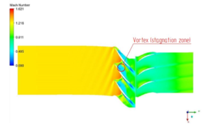
Figure 8.
Smooth rotor
Mach number distribution in blade-to-blade plane at the 98% span
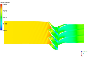
Figure 9.
With casing treatment ( casing treatment hidden)
Mach number distribution in blade-to-blade plane at the 98% span
Needless to say, casing treatments are a good way to improve transonic stage performance. Circumferential grooves are the better choice as their application on an existing rotor design entails a much lower performance penalty than axial slots. [4]Conclusions and future works
According to obtained results the SM improvement can achieve up to 13 %. The efficiency of such treatment was increased by 0.5%, however, the system remained at the same level. This is also a positive indicator, because there are no efficiency losses by using such treatments.
Also, it must be mentioned that this treatment reduces the mass of the casing, which is a benefit for aircraft design.
Optimization of groove shape is also an interesting and important field of investigation. Moreover, tip injection is the most promising way to have an influence on stationary zones and likewise requires special attention.
References
[1] Kim Jin-Hyuk, Dae-Woong Kim, and Kwang-Yong Kim 2013 Aerodynamic optimization of a transonic axial compressor with a casing groove combined with tip injection. Institution of Mechanical Engineers, Part A: Journal of Power and Energy vol. 227 8 : 869-884.
[2] Seleznev K P, Podobuev Y S 1957 Theory and calculation of axial and centrifugal compressors. — Leningrad: Engineering literature
[3] Hembera M., Kau, H. P., & Johann, E. 2008. Simulation of casing treatments of a transonic compressor stage. International Journal of Rotating Machinery
[4] Beheshti B. H., et al. 2005 Performance enhancement in transonic axial compressors using blade tip injection coupled with casing treatment. Proceedings of the Institution of Mechanical Engineers, Part A: Journal of Power and Energy 219.5: 321-331.
[5] Reid L., Moore R. D. 1978 Design and overall performance of four highly loaded, high speed inlet stages for an advanced high-pressure-ratio core compressor.- NASA-TP-1337, E-9302,122
[6] Fujita H., Takata H. 1984 A study on configurations of casing treatment for axial flow compressors Bulletin of JSME..№. 230. – С. 1675-1681.
[7] Cevik M. 2013 Axial Compressor Gas Path Design For Desensitization of Aerodynamic Performance and Stability to Tip Cl