


Development of the virtual experimental bench on the basis of modernized research centrifugal compressor stage test unit with the 3D impeller
A A Aksenov, A M Danilishin, А М Dubenko, Y V Kozhukov
Abstract. Design modernization of the centrifugal compressor stage test bench with three dimensional impeller blades was carried out for the possibility of holding a series of experimental studies of different 3D impeller models. The studies relates to the problem of joint work of the impeller and the stationary channels of the housing when carrying out works on modernization with the aim of improving the parameters of the volumetric capacity or pressure in the presence of design constraints. The object of study is the experimental single end centrifugal compressor stage with the 3D impeller. Compressor stage consists of the 3D impeller, vaneless diffuser (VLD), outlet collector — folded side scroll and downstream pipe. The drive is a DC motor 75 kW. The increase gear (multiplier) was set between the compressor and DC motor, gear ratio is i = 9.8. To obtain the characteristics of the compressor and the flow area the following values were measured: total pressure, static pressure, direction (angles) of the stream in different cross sections. Additional pneumometric probes on the front wall of the VLD of the test bench have been installed. Total pressure probes and foster holes for the measurement of total and static pressure by the new drainage scheme. This allowed carrying out full experimental studies for two elements of centrifugal compressor stage. After the experimental tests the comprehensive information about the performance of model stage were obtained. Was measured geometric parameters and the constructed virtual model of the experimental bench flow part with the help of Creo Parametric 3.0 and ANSYS v. 16.2. Conducted CFD calculations and verification with experimental data. Identifies the steps for further experimental and virtual works.
Legend
| b [-] dimensionless width
D [-] dimensionless diameter h [J∙kg-1] head ṁ [kg∙s-1] mass flow n [-] mode number P [Pa] pressure T [K] temperature U [m∙s-1] peripheral velocity y+ [-] wall distance in normal direction Z [-] number of blades Π [-] total to total pressure ratio β [-] loss coefficient |
ρ [kg∙m-3] density
η [-] efficiency coefficient ψ[-] head coefficient Φ[-] conditional flow rate coefficient Subscripts 0, 1, 2,… — specified section p, d, i — polytropic, dynamic, internal inl., out — inlet, outlet Superscripts *- total parameters
|
- Introduction
One of the main industries is the power engineering industry, which includes energy machines such as centrifugal compressors. Pressure head and efficiency requirements increases on the modern centrifugal compressors [13]. Continues appears the need in the production of high-performance, high-pressure 3D impellers. The use of centrifugal compressors with 3D impellers is now very important to the linear compressor stations of the unified gas transportation system of JSC «Gazprom». It is known that over time the gas field is depleted , thus changing the pressure, flow rate and gas composition, in this connection, to reduce the capital costs are used replaceable flow parts, which do not require changes of housing parts of gas pumping unit. Also this is especially relevant for all enterprises nitric industry for ammonia production, as well as processes for gasoline reforming, diesel hydrotreater, gas topping, where multistage centrifugal compressors are used as is compressed machines. In some conditions specified by the customer, it is impossible to carry out a full replacement of replaceable flow parts with the stator part and limited to the replacement of impellers, cutting existing flow parts and the installation of additional elements, such as in [7.9]. Similarly these impellers are widely demand in units of the turbocharging of the combustion engines [11].
In the past decade, actively developing supercomputing cluster technology, which allowed the use the numerical simulation in the development of new machines and reduce the cost of subsequent experimental refinements, and in the ideal case, to abandon such at all. Have the development and of multi-parameter optimization methods, by which is automatically calculated dozens of choices of energy efficient flow parts of the centrifugal compressors [2]. It is also possible to use for the study of complex forms of inlet and outlet chambers and other elements, because the flow in them significantly effect on the entire flow in general [6]. However, today’s methods of numerical calculation of the flow in a centrifugal compressor are not able to fully reflect the effects that repeatedly observed experimentally (for example, during the formation of «wake-flow» at the exit of the impeller). Often, to accelerate the procedure for calculating the elements of a compressor flowing part is carried out individually, that cannot account for their mutual influence on each other. To save computation time is also used averaging time formulation, therefore it is impossible to solve the time-dependent processes occurring in the flowing part. There is a need for a transient calculations on the performance ends, where is most pronounced flow separation and phenomena related to the loss of stability, as the local – prestall, rotating stall and global — surge. That requires higher computational resources, especially when solving problems with inlet and outlet chambers. However, there are developing methods, significantly accelerating the transient calculation, such as non-linear harmonic balance [1,4].
In studies [3,12] obtained the modeling of the «medium flow» centrifugal compressor stages performance, which of qualitatively and quantitatively the same as the full-scale experiment in the framework of permissible in engineering calculation error ± 2,5% in the zone of optimal performance mode. For other modes should further explore other turbulence models and methods of numerical solutions, allowing low energy losses associated with flow separation, as well as emerging non-stationary processes.
Summarizing the above, the aim of this work is to develop a virtual bench to perform comprehensive numerical calculations of the centrifugal compressor stage performance. The main development objectives of a virtual bench:
- The ability to simulate the experiment.
- The ability to simulate inconsistent modes of elements of a flowing part with a view to its correction.
- The possibility of multicriterial and multiparameter optimization of the impeller.
- The possibility of transient calculations.
The basis for the development of a virtual model of the bench is a full-scale training bench, upgraded to the possibility of carrying out research, which conducted an experiment for verification of numerical calculation.
- The design procedure with constraints
If there are insuperable geometrical restrictions, it is offered to use a virtual bench concept for study of engineering decision variants. It allows conducting tests, researches of both model, and full-scale objects. There are similar experimental bench developments [8], but for the purpose of the transient phenomena studying in a flowing part. It is expected that with the help of modern methods of multi-criteria and multiparameter optimization to carry out optimum geometrical parameters selection. In cases of modernization, operating on ammonia compressors often seeks to establish a flowpath with a nominal consumption by 25-40% larger than the original, while not changing the compressor housing. It is necessary to not install new piping installation, sometimes you want the opposite effect with decreasing consumption and pressure in connection with the improvement of technological process of target units [5, 10].
In such instances, the inlet and outlet chambers executed in the housing are left invariable. By increase in compressor productivity in not upgraded inlet and outlet, devices there are additional losses. Occurs research problem of the uncoordinated work of the last stage and the existing outlet chamber. Collaboration modeling of last stage and outlet chamber during their uncoordinated work causes special difficulties in calculations. In this study, such option is investigated: the impeller has nominal productivity more than the output chamber for 40%.
The following actions should be made to this task:
1) Performing measurements of geometrical setting parameters (fig. 3 a, b).
2) Parametrical model development (fig. 3 with, d).
3) Numerical model solution of setting (fig. 3 e, f).
4) Carrying out verification of the initial machine. (fig. 3 g).
5) Carrying out optimization with the existing constrains.
6) Carrying out the confirming tests.
In the figure 1 the procedure of the similar analysis performed according to points 1-4 is submitted.
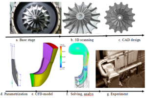
Fig. 1 The design procedure
According to the concept of the impeller was made using digitized laser 3d scanning. In the 3d scanning process the cloud of points which was transformed to the .stl format and then the solid-state CAD model was constructed. As the device of scanning was used the Faro scanner hand equipped to 7 joints and a mobile laser head of Metris Model Maker that allows to conduct 3d scanning of irregular shape products up to 2.5 meters in size with an accuracy from 0.04 mm. Measurement of flow parts and clearances was made by regular measuring tools. Then the parametrical model (CFD-model) about which it will be told below was constructed.
- Subject of research
| Table 1. The basic dimensionless parameters of stage. | |
| Parameter | Value |
| D0 | 0.571 |
| D1 | 0.571 |
| Dh | 0.207 |
| D4 | 1.445 |
| D2’ | 1.056 |
| b1 | 0.182 |
| b2 = b3 | 0.087 |
| b4 | 0.116 |
| Z2, pcs. | 15 |
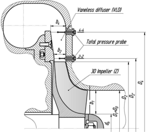
Fig. 2 Scheme of the object of study
The subject of research is a high flow centrifugal compressor stage model (Fig.2), consisting of impeller with 3D blades and vaneless diffuser installed in the experimental bench. Integral parts of the bench are axial inlet and outlet chamber (the volute coiled to one side). The main dimensionless geometrical parameters of the flow part are provided in Table. 1.
- Experimental bench
Training experimental bench is adapted to receive pressure data in 4 sections (Inlet, 2-2, 4-4, Outlet) and temperature parameters of the inlet and outlet of the compressor. Experimental Bench before the modernization had 1-point measurements of total and static pressure in sections 2-2 and 4-4, and had no insulation of the housing and pipes.
In the course of works on modernization, on the front wall of VLD were installed, additional receivers – total pressure probes and holes for measuring total and static pressure for a new drainage scheme Fig.3 b. This allows conducting full-scale experimental study of centrifugal compressor impeller and vaneless diffuser. Also was carried out the insulation of the compressor housing. Selection of the static pressure in the cross section 2-2 and 4-4 was carried out in six and five points, respectively. Total pressure measurements were made in four points along the width of the channel. The definition of the capacity was determined in the cross section 0-0 in accordance with the established measurement instruments in Fig. 3 a.
The drive unit for the bench is a synchronous DC motor with 75 kW. The electric motor through a multiplier lets you adjust the rotational speed of the bench in the range of 5800-11200 rev/min.
After commissioning test, measurement parameters were performed on five modes in the zone of optimal performance and appearance of the area of transient processes. The number of revolutions of the rotor in the tests was set at 8000 rev/min.
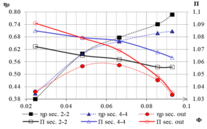
Fig. 3 Total pressure probe locations in а) 0-0 section b) 2-2, 4-4 sections
Расчет характеристик велся по следующим основным формулам:
Conditional flow rate coefficient is
(1)
Polytropic efficiency at full range of parameters is
(2)
Internal head coefficient is
(3)
Theoretical head coefficient is
(4)
Total to total pressure ratio coefficient
(5)
Fig. 4 Performance of centrifugal compressor
As expected the obtained performances (fig 4) of the mismatched elements, namely the optimal mode of operation of the impeller is in the range of Φ=0.095-0.11. Because of the stage «stiffness», right side of the impeller performance is cut.
Optimal work zone of the outlet chamber — volute in the range Φ = 0.05-0.065. This problem is typical for the last stages of the multistage compressors for modernization to increase their productivity at constant inlet and outlet chambers. To solve the problem, last stages should be designed so that the angle of entrance flow in the outlet chamber remained within (+-) 2-4 degrees from the nominal design. It is also recommended to unload on the head level, to reduce the flow rate at its output. These activities provide an acceptable mutual work of the modernized last stage and outlet chamber.
In our case, we use the concept of a virtual bench for studies on this problem with the help of multi-criteria methods and multi-parameter optimization, but first conduct verification of numerical calculation to determine the error for the object.
- Virtual experimental bench
CFD model has full sweep angle of the elements with inlet and outlet pipes. Inter gap and dummy piston seals at the base disk have not been simulated. The calculation is based on RANS – method (Reynolds-averaged Navier-Stokes) with Low-Re turbulence model. Was built a detailed computational mesh in the boundary layer, where the 1st grid node should be in the viscous sublayer (y+ = 0 … 2). A CFD Solver of Ansys CFX 16.2 was applied. The work fluid is air (ideal gas). The outcome of the mesh independence studies provides the grid with app. 40 million cells.
Were selected the following boundary conditions (BC): the inflow direction is assumed as normal to the axial inlet of the computational domain. The simulations were run with P*inl and T*inl in inlet boundary and mass flow ṁout at outlet boundary. The walls were assumed as adiabatic. The inlet and outlet BL conditions are listed in Table. 2. The Table also provides the conditional coefficient of flow rate (Φ) and mass flow (ṁ). The BC were determined by the outcomes of the full-scale experiment.
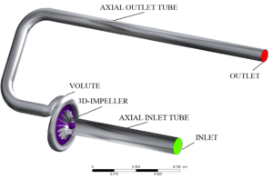
Fig. 5. CFD model and BC of virtual experimental bench
Table 2. The parameters set on the inlet and outlet BC of the computational domain
| Mode, n | Φ | T* inl, K | Р*inl, Pa | ṁ, kg∙s-1 |
| 1 | 0.093 | 294.35 | 99051 | 0.504 |
| 2 | 0.085 | 294.60 | 99327 | 0.465 |
| 3 | 0.066 | 294.55 | 99830 | 0.363 |
| 4 | 0.048 | 294.05 | 100179 | 0.264 |
| 5 | 0.025 | 294.60 | 100650 | 0.136 |
The calculation was carried out at the supercomputer center “Polytechnic” with heterogeneous cluster HPC Tornado using 8 nodes. The parameters of one node of the cluster: RSC Tornado – 2 CPU with 14 cores (2xXeon E5-2697v3 2.6 GHz 64 GB RAM). In sum — 712 nodes (19936 cores).
Calculation of one mode is 21 hours.
- Verification results
All modes developed the converging solutions (example of convergence history for mode 1 shown in Fig. 5), defined by the following parameters within the computational domain BС:
- the fall of the level of root-mean-square (RMS) residuals below 10—4,
- the relative error in mass and energy imbalance is ~ 1 ∙ 10-2 %,
The controlled values of integral parameters in the control sections do not change from iteration to iteration.
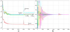
Fig. 6. Convergence history for RMS residuals mass and momentum, energy (a) and imbalances within computations domains (b)
In the figures 7,8,9 are shown experimental characteristics of object with comparison virtual bench numerical calculation of the characteristics.
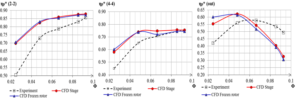
Fig. 7. Verification results for polytropic efficiency (total) at the outlet of the impeller, VLD, volute.
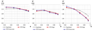
Fig. 8. Verification results for pressure ratio (total) at the outlet of the impeller, VLD, volute.
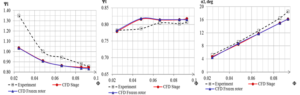
Fig. 9. Verification results for internal, theoretical head and flow angle at the outlet of the impeller, VLD, volute.
The calculation for the verification was conducted with interfaces «stage» and «frozen rotor» between the impeller and volute. The chart Fig. 7 shows good agreement between the results of calculation and experiment in the area of optimal mode Ф=0,093-of 0.085 for the impeller. However, when considering areas with low productivity errors increases significantly. This is due to the appearance of low-energy zones of separation flow associated with the deterioration of the flow conditions of the blade apparatus in these regimes. Also, there is an overestimation of the characteristics, because not taken into account the thermal effect associated with the occurrence of non-stationary processes (fig. 9). Determination of the optimal operation mode of the output device is complicated by the fact that starting with the 3 modes the impeller operates when α2<16 (fig.9), indicating that the early appearances of non-stationary phenomena so there needs a transient calculation. This thermal effect increases internal head in the impeller and give big error for polytrophic efficiency in stationary results, also it can be imperfect of the semi-empirical turbulence model.
In Fig. 8 shows plots of the relationship of the total pressure on the control sections, there is an exact match on the first three modes for Impeller and VLD, however, after the volute there is a big error, probably related to the increase of the error in the numerical calculation due to the volute.
- Parametric model
To solve the problem a parameterized model of the impeller was developed (fig. 11). For the geometrical parameters of the model the variables names and were assigned and the ratios between them were adjusted. In total we used 16 variables defining the geometrical model of the the impeller flow part. The model allows to build semi-open and closed impellers. Ansys BladeModeler used for the parameterization of impeller flow part geometry parameters.
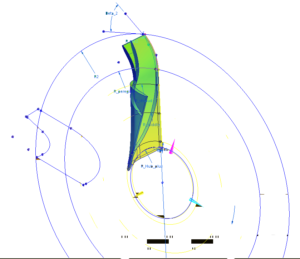
Fig. 10. Parametric model
The Optimization will perform on a heterogeneous cluster HPC tornado in SPbPU supercomputer center using the multi-objective optimization technology IOSO (Indirect Optimization based on Self-Organization). The following target parameters will select: impeller adiabatic efficiency, impeller pressure ratio, head coefficient, stage adiabatic efficiency, and stage pressure ratio. The ranges of limitations of the geometric parameters were determined in terms of the design constrains.
- Conclusions
Because types of machines a lot, you should use original verification data, if there is no specialized experimental database. Error obtained during the verification can be used at optimum modes to evaluate the effectiveness of the every element. This is due to the fact that the existing methods of numerical analysis does not fully reflect the effects of flow separation and because of the mismatch of the optimal mode of elements. Thus one cannot say about the admissibility of the results of the inconsistent elements stationary calculation, therefore, it seems for a correct evaluation requires a transient calculation. However, the results are acceptable for verification of the characteristics of the impeller in the area of optimal mode at the stationary calculation, which requires much less computational resources compared to unsteady calculations.
Developed a parametric model will be used to conduct multi-criteria optimization to verify the concept design of the revamped compressors. The works will be conducting numerical and field experiment produced for the flowing part of the impeller and VLD, assessment of the effectiveness of the concept and development of recommendations on modernization of centrifugal compressors.
References
- Boldyrev, Y., Rubtsov, A., Kozhukhov, Y., Lebedev, A., Cheglakov, I., Danilishin, A. Simulation of unsteady processes in turbomachines based on nonlinear harmonic NLH-method with the use of supercomputers // CEUR Workshop Proceedings. Volume 1482, 2015, Pages 273-279.
- Danilishin A., Kozhukhov Y., Yun V, Multi-objective optimization for impeller shroud contour, the width of vane diffuser and the number of blades of the centrifugal compressor stage based on the CFD calculation. IOP Conference Series Materials Science and Engineering 08/2015; Volume 90(1):012047. DOI:10.1088/1757-899X/90/1/012046
- Danilishin A., Kozhukhov Y., Gileva L., Lebedev A. Verification of the CFD calculation on a supercomputer of medium flow model stages of centrifugal compressor. Russian Supercomputing Days: Proceedings of the international conference (September 26-27, 2016, Moscow, Russia). Moscow State University, 2016.
- He L. and Ning W., «An Efficient Approach for Analysis of Unsteady Viscous Flows in Turbomachinery”, AIAA Journal, Vol.36, No.11, 1998.
- Kovalevskiy N.L., Kuz’min V.Ye., Spirin N.Yu., Chernyavskiy L.K. 25% productivity increase of К1290-121-1 compressor for large-capacity ammonia production. Compressors & Pneumatics. 2009. №1 pp.
- Kozhukhov Y.V., Yun V.K., Reshetnikova L.V., Prokopovich M.V. Numerical Investigation of Different Radial Inlet Forms for Centrifugal Compressor and Influence of the Deflectors Number by Means of Computational Fluid Dynamics Methods with Computational Model Validation. IOP Conference Series Materials Science and Engineering 90(1):012047 · August 2015. DOI: 10.1088/1757-899X/90/1/012047
- Kuzmin V.E., Primak A.N., Chernyavsky L.K. The most significant reconstructions and modernizations of centrifugal compressors, executed JSC «SIF «Nevintermash».Compressors & Pneumatics 2011 №1. pp.11-15.
- Лопулалан, Хенри Доминггус. Виртуальный стенд для исследования нестационарных процессов в ступени центробежного компрессора [Текст]: дис. канд. техн. наук: 05.04.06 / Лопулалан Хенри Доминггус; Санкт-Петербургский государственный политехнический университет.
- Semakov A., Evdokimov V., Reprintcev A., Liubimov A. Modernization of centrifugal compressors on nitric production facilities. Compressors & Pneumatics. 2013. № 3. pp. 2-4.
- Semakov A., Evdokimov V., Reprintcev A., Liubimov A. Increase of Capacity by 35% and Efficiency Raise of the Technological Air Centrifugal Compressor 101J in Ammonia Production. Technical Preprints Nitrogen+Syngas 2015. 2015. pp. 415-424.
- Simonov A.M., Study of the efficacy and optimal design of high-pressure centrifugal compressor stages. pp. 164 – 188. / Works of scientific school of the compressor design SPbPU. Under the editorship of Professor Yu. b. Galerkin. – Ed. St. Petersburg State Polytechnical University, St. Petersburg, 2010 — 670 p.
- Yablokov A.M., Kozhukhov Y.V., A.A Lebedev An ansys CFX numerical study of a low-flow stages centrifugal compressor // Nauchno-tekhnicheskie Vedomosti SPbGPU. Vol. 4(231)/2015. Ed. SPbSPU. pp. 59 – 69.
Yun V.K. The use of advanced technologies to improve the economic performance of the centrifugal compressor. Gas industry №9, 20